Magnetic Loop - Software
September 2015
The Loop is working fine, but two things are bothering me.
1- The loop was calculated to have a range from 160 to 40 meter. Unfortunately the loop can't be tuned to 40m. Too much 'L'.
2- The tuning with a DC motor and some up and down buttons is a hassle.
To solve problem 1. the loop has to be made smaller. Less 'L' so I get more headroom in the high band (40m).
I have plenty of 'feetroom' on the lowest band (160m).
To solve problem 2. I need a very accurate and easy to control Vacuum Cap driver. A stepper motor has both!
But, for a stepper motor a control program is required.... And such a program for this application is not available.
I started searching the web for 'off the shell' stepper motor controllers.
Most of them have no smart logic on board and all the control you have to build (program) yourself.
But I found a board called "Motor Hawk" which has USB control and is delivered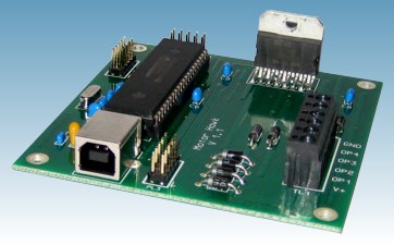
with a dll for all the actions towards a stepper motor.
It comes with a CD with the dll and very useful program examples in C++
and Visual Basic.
Here the small controller board, developed and sold by PC-Control in the UK.
It's a 4-phase Bi-Polar (or hybrid) stepper motor (or two DC motors) controller
and can handle up to 36V-2A/phase.
There are also 8 digital inputs and 5 digital outputs available for general use,
with 4 of those inputs configurable as automatic limit switch inputs for motion control applications.
Here the updated vacuum C control with the stepper motor.
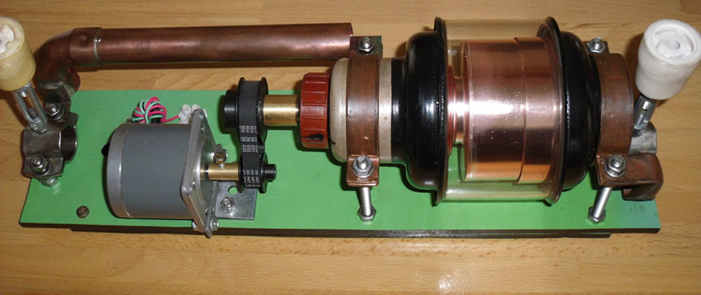
It's a lot simplified. No end-switches, no position potentiometer.
Just a stepper motor, some tooth pulleys and a tooth belt, which are not hard to find on the web.
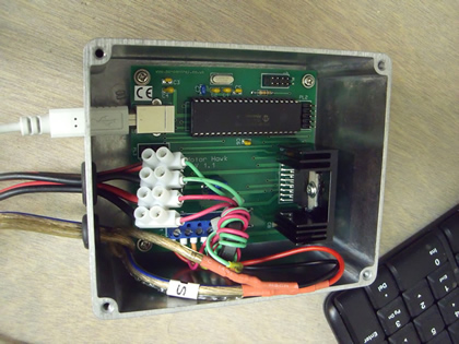 Here you see the board in its enclosure.
At first I wanted to mount the controller near the Loop, so the motor wires remained short. But then I would need a 15 meter long USB cable. Not recommended. In addition, the controller also needs a DC power supply** of a few amps to feed the stepper.
So I decided to keep the controller in the shack and connect the stepper motor by a 4x 1.5 mm² cable.
**) My stepper, a Minebea 23LM-C303-05, needs 3.5V-1.4A/phase.
I had an old Philips power supply, 12Volt-3Amp, perfect for the job.
With 12V, two shunt resistors in the motor leads are needed, generate a lot of heat. :-( So I calculated the voltage drop across the 15 meter long leads, added the voltage drop of the board and
adjusted the output voltage of the power supply accordingly (+/- 7 Volt). The stepper gets 3.5 Volt and no shunts needed.
Digital switching produces RFI. Something we do not like. :-(
This board is no exception. I installed a 100nF ceramic capacitor between each motor output and ground (0V).
The wires are wrapped five times through a ferrite toroïd. Close to the stepper I also used a toroïd core.
The board is mounted in an alloy box (with lid) and grounded to the box with 100nF. The box itself is grounded via the mains ground.
As a result, RFI is reduced by 95%.
(more testing to do...)
To write a controller program for this board it was "back to the classroom" for me.
Although I had some programming experience,....(IBM mainframe systems programmer).........., that was ten or more years ago!
It took me a while.... I studied visual basic from MS...
(Visual Studio 2013)
...and with lots of trial & error.....,
I finally managed. MagLoCon, november 2018, Version 3.2.2
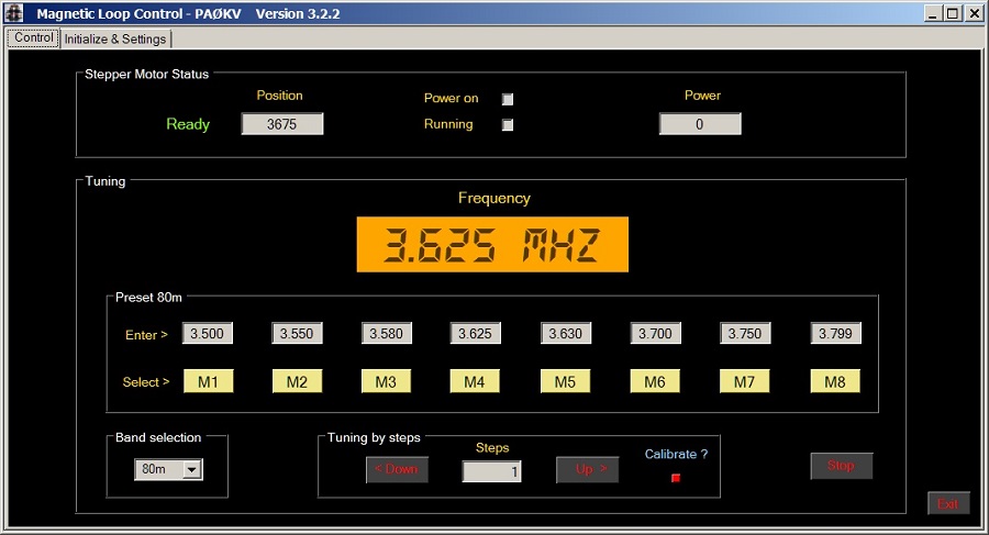
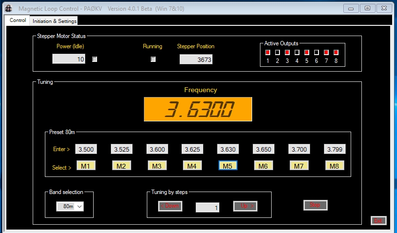
Control screen (tab). Band selection for 160-80-60-40m. Each band has 8 memories.
The display shows the chosen memory frequency. Tuning by steps to fine tune for 1:1 SWR.
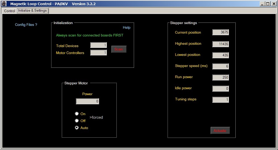
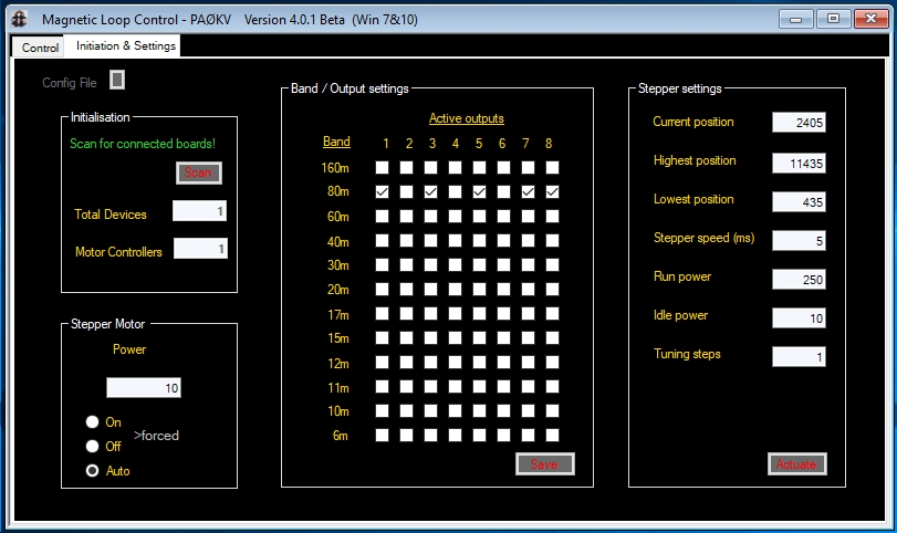
Init screen (tab). Program first needs to initialize the stepper board. (Searching the USB devices connected.)
Stepper settings for: stepper motor power range 0-250, stepping rate in ms, default tuning steps for Up and Down buttons.
Stepper power can be forced "On" (max) or "Off" (zero) for test purposes.
The program uses 1 control file and 4 memory files (xxx.cfg). They are read at initialization when a stepper control board is found.
Files are saved by the Actuation button and by the memory Store buttons.
I also made the loop smaller. It's now 3,4 meter in diameter and is tunable from 1.75 to 7.3 Mhz.
Mission accomplished!!
I created a rar file containing the program, the config files and a manual.
You can download
it here> MagLoCon-V3_2_2. (New release! Nov. 2018, read Manual & Release.log!)
Any questions? Mail me!
News!! September 3 - 2022
I moved to the countryside and was able to hang an 80 meter delta loop antenna between the trees.
The magnetic loop antenna is no longer used. This also ends my interest in the control software.
I have decided to discontinue support and hereby offer the source program, with all rights, for sale.
A potential commercial product/application!
Purchase price and conditions in consultation.
----------------------
April 2018
A ham asked me why I limited the number of bands to 4 and why I did not use the outputs of the controller.
For my magnetic loop I do not need more bands, simply because the antenna can not be resonated in other bands.
I do not immediately see an application for the outputs (and inputs) either.
But I did build a beta version with all (12) HF bands (6-160m), and switchable outputs adjustable per band. :-)
Who knows, maybe I'll build a smaller loop some day to cover the higher bands....